

The Ins & Outs Of An Aircraft’s Electrical System
Modern transport aircraft are power-hungry machines. In the past few years, they have become more and more electricity dependent. Even the most critical components of aircraft such as the flight control systems require electricity for proper functionality. The latest generation airplanes such as the Boeing 787 and Airbus A350 are known as More Electric Aircraft (MEA) due to their usage of electricity for key aircraft equipment.
This article will focus on how the electrical system in an aircraft works.
.jpeg)
Airbus A350 relies heavily on electrical power. Photo: Vincenzo Pace I Simple Flying
Alternating Current (AC) or Direct Current (DC)
It is common to find DC power as the main source of electricity in smaller aircraft. For example, in most turboprop aircraft such as the ATR and the Dash 8s, the DC motors act as starter generators during start-up. In larger aircraft, AC power is used. AC motors have a better power-to-weight ratio and are simpler in design. As bigger aircraft require a lot more electrical power, DC motors and a DC power system become impractical.
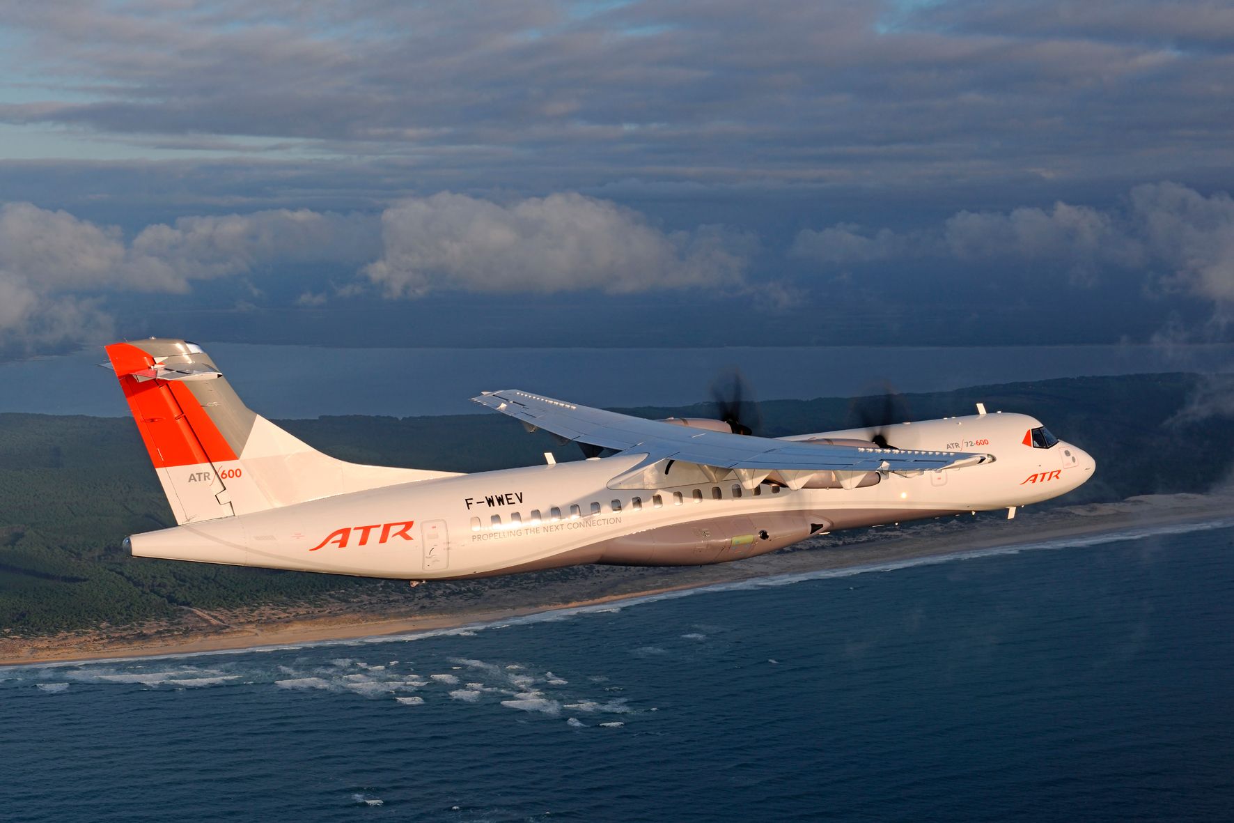
Turboprops like the ATR uses DC power as the main source of electricity in the aircraft. Photo: ATR
In all aircraft, there is equipment that requires either DC or AC electrical power. So, in DC systems, something called an inverter is used to convert DC to AC. In the case of an AC system, Transformer Rectifiers (TR) are used to convert AC to DC. Some turboprops have AC generators which supply variable frequency power to some certain equipment such as the wipers and anti-icing systems. But these generators are not as powerful as the DC generators.
How the main electrical system in an aircraft works
There are two main types of electrical systems. One is called the split bus system and the other is called the parallel bus bar system. A hybrid system called a split parallel bus bar system also exists. Before we look into the details of these systems let us first look at the individual components of an electrical system.
The batteries
Batteries are the most basic source of electricity for an aircraft. In large aircraft, there are two individual batteries for redundancy purposes. The batteries are used to first power up an aircraft. Once the batteries are on, they can be used to start the Auxiliary Power Unit (APU). With the APU available, the batteries are disconnected from the aircraft’s electrical system if they are fully charged and remain so for the rest of the flight. As batteries are the last resort for power in the event of a full electrical failure in flight, they are not used to power the aircraft during any phase of the flight. Many aircraft uses Nickel Cadmium batteries.
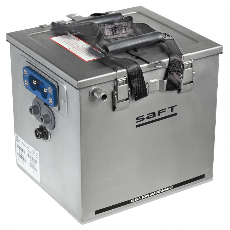
A Nickel Cadmium battery used in Airbus A320. Photo: Saft Batteries
The Generators
There are two types of generators – DC generators and AC generators, which are most correctly known as alternators. The main difference between a DC generator and an AC generator in an aircraft electrical system is that, in the former, the armature of the generator turns while in the latter, the field or the magnet turns around a stationary armature.
As most large airliners use AC generators, we will talk about them in this article. The AC generators used in aircraft are three-phase generators. This means that the windings around the generators are arranged in such a manner that each phase is 120 degrees out of phase with the other. The outputs of an AC generator are connected in what is called a star method. Here the three phases are joined to form a neutral point that is grounded.
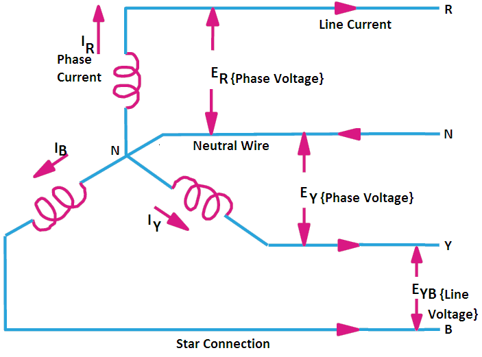
Two voltage readings can be derived from such a connection – a phase voltage and a line voltage. The phase voltage can be measured by taking the voltage between the neutral point and a line lead while the measurement voltage between two lines gives the line voltage. In an aircraft, the line voltage is about 200 volts, the phase voltage is about 115 volts, and the frequency is 400 Hz. So, an electrical system of an aircraft is said to be a 115V/200V/400Hz/3 Phase system. The 400 Hz is the optimum frequency of the generators used in aircraft.
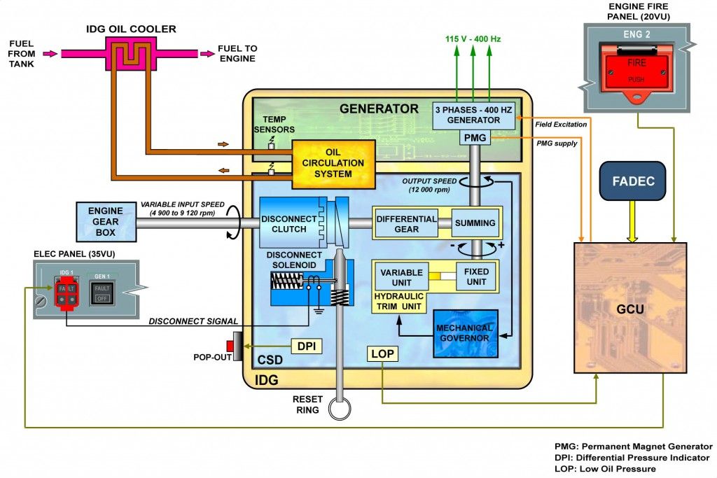
In aircraft, the generators are rotated by the engines. This means that the speed or the frequency of the generator changes with the changes in engine speed. During a flight there will be changes in the speed of the engines and this can affect the rotational speed of the generator. So, controlling the speed of the generator to maintain its frequency becomes critical. For this, a device called a Constant Speed Drive Unit (CSDU) is used.
The CSDU consists of a hydraulic pump run by the engines. The pump then runs a hydraulic motor. When an under speed or an over speed signal is sent by the generator to the hydraulic pump, it varies the fluid sent to the hydraulic pump to control the speed of the generator. Most IDGs can maintain the frequency within 5{5376dfc28cf0a7990a1dde1ec4d231557d3d9e6448247a9e5e61bb9e48b1de73} of the required 400Hz.
The Bus Bars
The bus bars are metallic bars used to transfer electrical power from the sources like a generator to the individual equipment. In an aircraft, there are many individual bus bars. The batteries, for example, have their bus bars and there are main bus bars which are supplied by many sources such as the engine generators, APU generator, external power, etc. You will gain a better understanding of the bus bars when we look at the split bus bar and the parallel bus bar system in the upcoming paragraphs.
One of the most important buses in an aircraft are the Hot Battery buses. These bus bars are hot wired to the batteries and function even when the aircraft is fully shut down. Engine fire extinguishers and evacuation slide systems are powered by a hot battery bus.
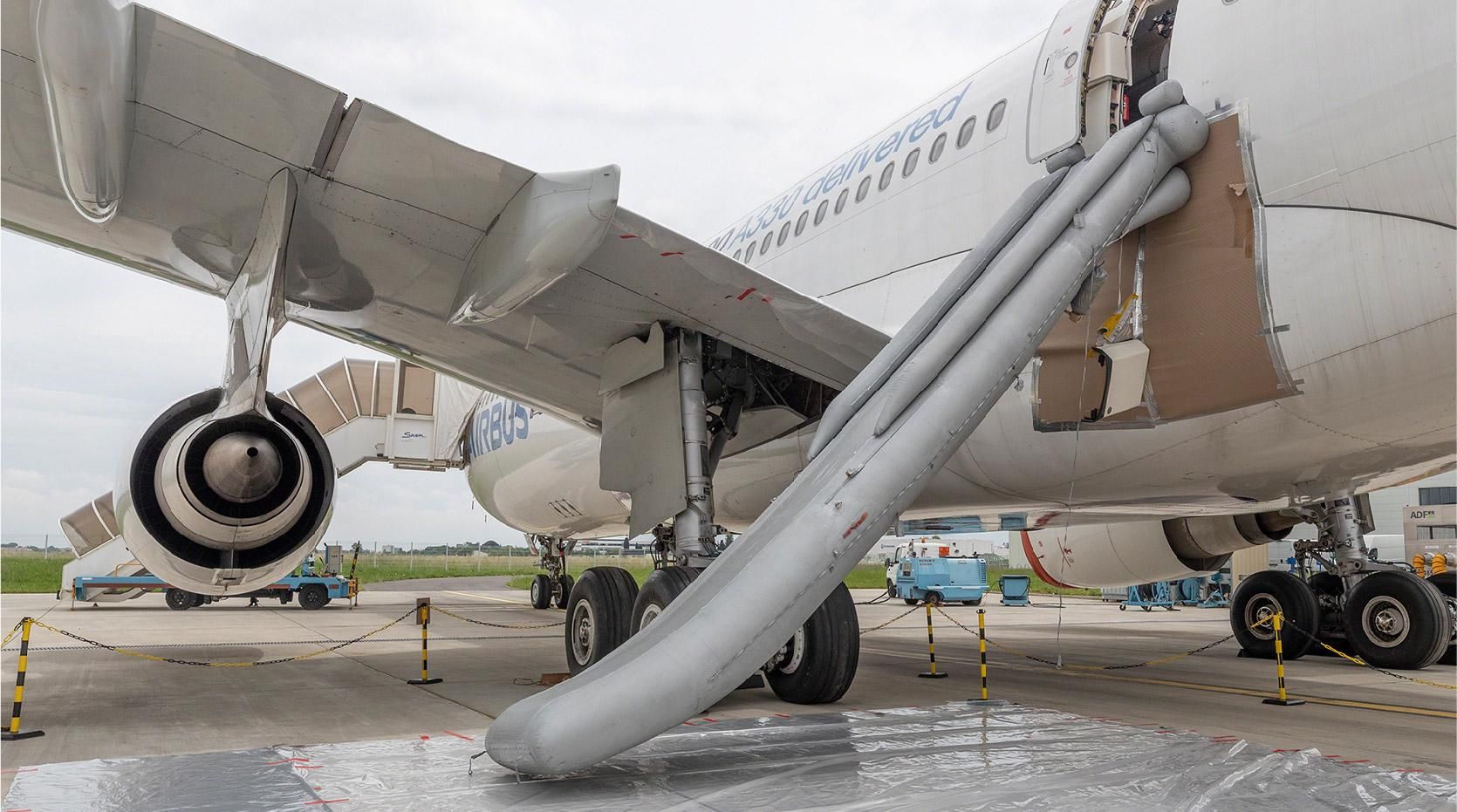
Evacuation slides are powered directly by the batteries. Photo: Airbus / Sylvain Ramadier
The Parallel Bus Bar System
Parallel bus bar systems are rarely used in aircraft these days due to their complexity. It is mainly found in three or four-engine aircraft. As the name suggests in a parallel bus bar system, the generators are connected in parallel.
Before generators are paralleled, they should be synchronized such that the voltage output and the frequency of them are the same. Also, the phases A, B, and C on one generator must be identical to the phases A, B, and C of the second generator, the third generator so-and-so. This prevents damage to the generators. Keep in mind that once generators are paralleled, they work together and share the electrical loads.
In a parallel system, each generator has its bus bar connected by its generator circuit breaker. The bus bar consists of three individual bus bars for each phase (A, B, and C). These bus bars are then connected to a synchronizing bus bar via tie-breaker. The function of this synchronizing bus is to allow for parallel operation of generators. The Auxiliary Power Unit (APU) and the external power are also connected to the synchronizing bar.
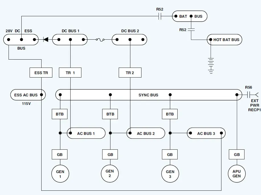
flight-mechanic.com
One of the main advantages of paralleled generators is that if one of the generators is to fail in flight, the remaining generators can share the load efficiently. The other advantage is that, again, if there is a generator failure, the system is not interrupted as the other generators remain to power the synchronization bus and thus the components connected to it. In older aircraft, like the Boeing 727, the flight engineer can play with the frequency of the generators in the aircraft. There are synchronization lights that illuminate when the generators are out of sync. The engineer can then manually control the frequency of the generator until the light goes off. If it does not get synchronized, the generator cannot be connected to the synchronization bus.
Split Bus Bar System and Split Parallel Bus Bar System
Most modern aircraft use this type of system. In a split bus bar system, each generator has its bus bar and there is no paralleling. Each generator individually powers its respective bus. If a generator fails in this system, the remaining generator powers the bus of the failed generator.
The Boeing 747 is the only modern airplane with a partial parallel system, called the split parallel bus system. In this system, there are two synchronization buses connected by a tie-breaker. As there are four generators in the aircraft, two generators supply each of the two synchronization buses. This type of system while still complex, has the advantages of both the split bus and the parallel bus system. Because the load-sharing capability is way better in a parallel system, the load on the individual generators is reduced in failure conditions.
To give you an example, we can compare the B747 system to that of another four-engine aircraft – the Airbus A340. The A340 uses a split bus bar system. In the A340, if there is a generator failure, the onside generator will power the failed generator bus. The remaining generators cannot help to accommodate the failed generator bus, as only the onside generator can. This means some load shedding is required to not overload the supplying generator.
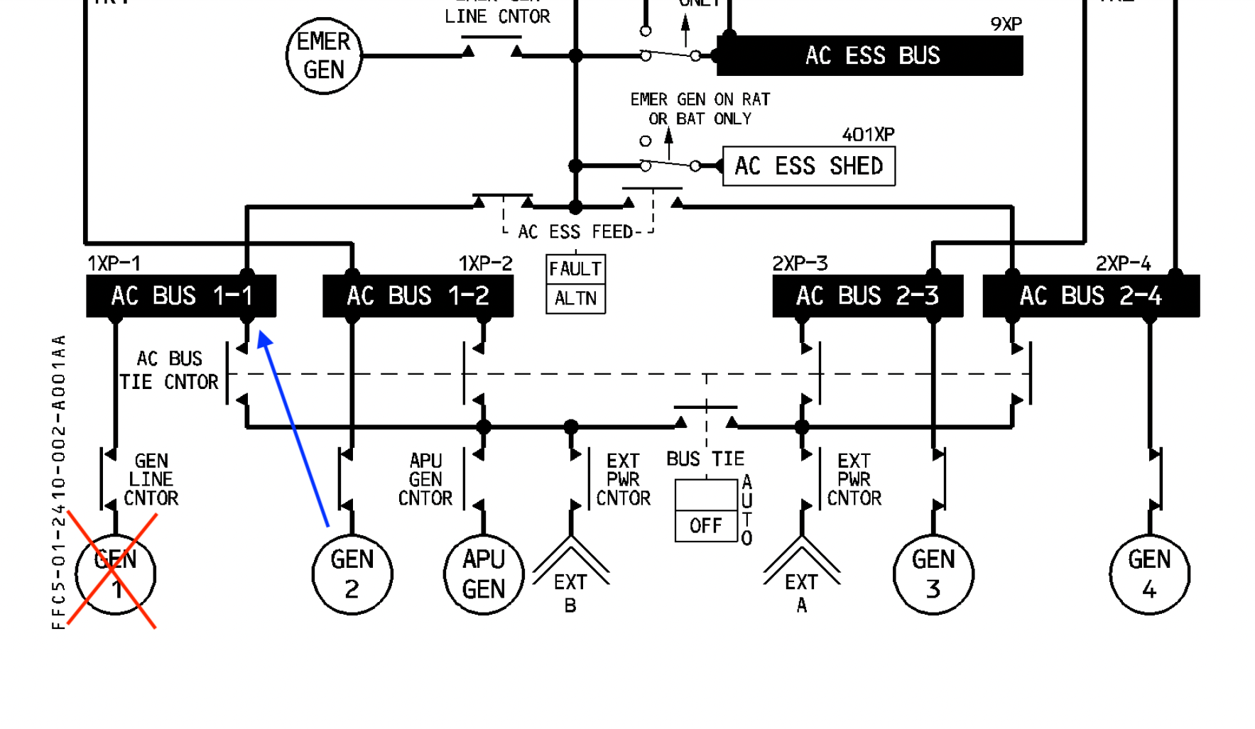
The A340 electrical system. Here, the number 1 generator has failed, and it is taken over by the onside number 2 generator. Picture: Airbus A340 FCOM
In the B747, the failure of a single generator have little to no effect on the electrical generation capacity of the aircraft. The three remaining generators are still connected to the synchronization buses. This means that the three generators can share the load and supply the failed generator bus through the synch bus. With this system it is possible to power all four AC buses in the B747 by a single generator (some load-shedding can be expected here as the aircraft is on one single generator). In the A340, the failure of three generators (one remaining), will completely shut down one side of the AC electrical system. If the two generators on the right are to fail, the right AC buses will lose power. This requires a lot of load shedding.
Emergency electrical system
All transport aircraft have backups for electrical systems. The generators, which are the primary source of electricity, are run by engines and a failure in the engine(s) can disrupt the workings of the generator(s). A fault in the generator(s) itself can stop it from functioning. Due to this reason, a means for emergency electrical power becomes necessary.
The Ram Air Turbine (RAT)
The RAT is a turbine that falls out of the aircraft in the event of loss of main electrical power. When the turbine runs it turns a hydraulic system. This hydraulic system then runs an emergency electrical generator which provides electricity for the essential systems in the aircraft.
The emergency generator is not as capable as a main aircraft electrical generator, so it powers only the most critical components that are essential for the safe operation of the aircraft. For a fly-by-wire aircraft, this means it can support some flight control computers and flight instrumentation.
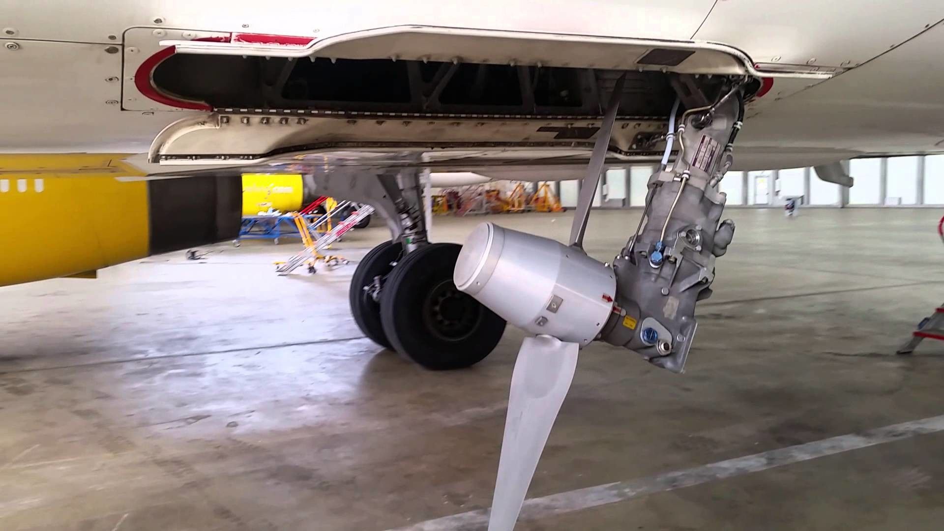
The RAT of an Airbus A320. Picture: monolib.net
The APU Generator
The APU can be started inflight in most airliners. The APU has its generator which is as capable as an electrical generator in an aircraft. With the APU generator operative, it can support a lot of non-essential and all the essential systems in an aircraft.
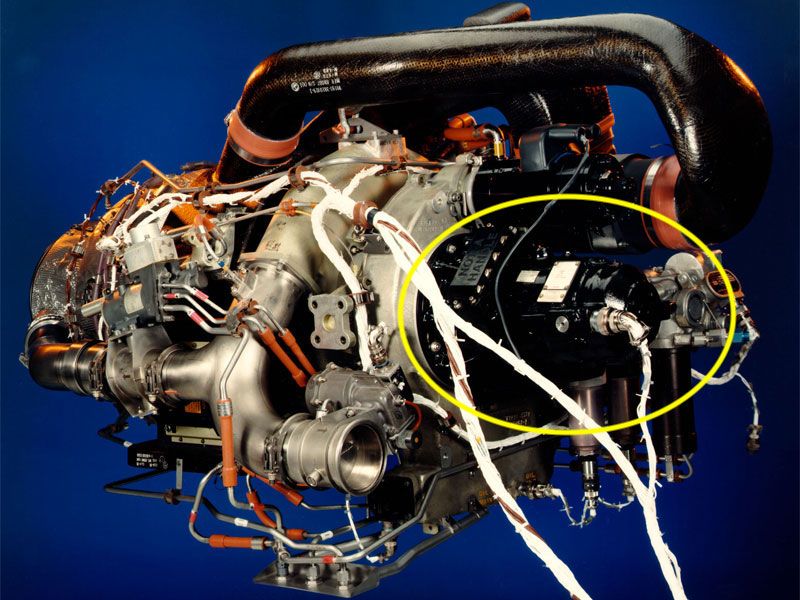
APU electrical generator. Photo: Honeywell
Aircraft batteries act as the last resort
The regulations require that the aircraft batteries last for a minimum of 30 minutes if it goes into battery-only power. In some aircraft with normal electrical systems running this may not be possible. In such aircraft, the pilots may need to shut down most of the equipment and rely on the very basic instrumentation to fly the aircraft.